Electronics & Robotics

♦ Testing the armature of an universal motor
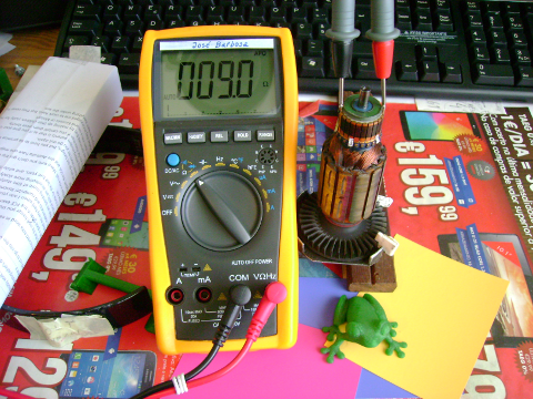 |
Test #1: 180 deg Resistance test To check the condition of the armature windings, the armature will probably have to be removed from the motor. However, if the motor design has external brush holders, we can unscrew the brush caps and remove the brushes. Depending upon brush size, this may allow access to the commutator without removing the armature from the motor. . The first check to see if your armature windings are shorted, is the 180° Resistance test. A volt/ohm meter can be used to check the resistance of the series windings connected between the two commutator bars of each coil. Set the meter to measure resistance (Ohms) and then measure the resistance from two commutator bars 180° across from each other. Rotate the armature and check the resistance between every pair of bars on the commutator. |
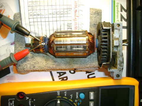 |
Test #2: Bar to bar Resistance test |
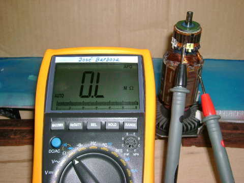 |
Test #3: Commutator bars to the iron armature stack Resistance test |
♦ Breadboard BJT, FET and Diode oscilloscope curve tracer
Is shown in the photo, supported by a stepper motor controller and driver with 4 transistors mounted in copper heat sinks.
At lower right: a stepper motor and a Futaba RC servo.

♦ My new Digital Storage Oscilloscope, RIGOL DS1074Z
And friends!


♦ Stepper Motor Controller and Driver Assembled in the rear Breadboard.

♦ Electronics Breadboard LAB.
I use it to test my circuits. If they work well, and it’s worthwhile, I will assemble them in a PCB.